 |
| CLICK ME :) |
my path

Wednesday, 28 December 2011
CONCLUSION
This conclusion means Introduction to ESE subject is finish up for this semester. Thanks a lot to Dr. Kamal, Mr. Redzuan and Mr. Rasli. Throughout the semester was fun and full of joy but at the same time study and practical is not being put aside. balanced between IQ and EQ is important to maintain our mind and also our body. Lecture given by Dr. Kamal and Mr. Rasli is needed to introduced us with this whole new ESE world. Practical with Mr. Rasli ensure that we can deal to make our own project in the coming semester. Industrial visit open my eyes and my mind how the situation inside the industry area, make us feel very anxious on what will happen to us in the future. Overall ESE class was awesome and thank you again to three great pillar that accompany us side by side throughout this semester. Hopefully we can see each other again next semester. :D
Sunday, 25 December 2011
~ DIGITAL ELECTRONIC ~
 |
| sample of digital electronic |
This week actually it was our last week for ESE subject. Therefore Dr. Kamal will brief us about the subject that we will take next semester which is Digital Electronic. WHY DIGITAL electronic? This because it has becoming part of almost everybody life. Digital Electronic can also be called the heart of electronic devices. This is because digital electronic control the function of electronic devices through it logic gate and binary number.
Digital electronic can be divided into three which are counting system, digital base-binary number and analog and digital signal. Logic level one of a finite number of states that a signal can have. Its usually represent by the voltage difference between the signal and the ground. In binary logic the two level are respond to binary 1 and 0.
 |
| sample of binary number |
Binary numeral system or base-2 system represents numeric values using two symbols, 0 and 1.In this numeral system we learn on how to apply mathematics operation such as addition, subtraction, multiple and division to our binary number. We also had been given exercise to improve our understanding on this binary mathematics operation. Besides that, Dr. Kamal also touch a little bit about circuit automation and electronic design automation. Electronic design automation is category of software tools for designing electronic systems such as printed circuit boards and integrated circuits.
 Thanks to Dr. Muhamad Kamal bin Mohammed Amin for the great introduction and planning for Electronic System Engineering throughout this whole semester.
  |
| THANKS A LOT :) |
Sunday, 18 December 2011
E+L+E+C+T+R+I+C
After an enjoy trip last week, we back to our workshop to continue what we left before. Finished with our circuit now we moved to electric part. In this session, im partner with Firdaus. We will assembly our own extension wire and pendaflour lamp. First, our lab instructor, Mr.Redzuan show us how to connect all the wire needed. He says we need to be careful because we deal with electricity that can cause serious problem if we play with it.
 |
| inside the plug |
 |
| sampe of [endaflour lamp |
 This is our last class with Mr. Ahmad Redzuan bin Mohd Hanapiah, our lab instructor. Thanks to Mr. Redzuan for all the guidance, advice and hardship in teaching us. THANK YOU
Friday, 9 December 2011
Canon Opto(M) Sdn. Bhd (INDUSTRY VISIT) 7/12
 |
| The first camera by Canon |
This week is so meaningful to us, SMJE students because we are having industrial visit at Canon Opto(M) Sdn. Bhd. on behalf our introduction to Electronic System Engineering study.The purpose of industry visit is to introduce us about industry.
This is my first experienced to visit a factory and see with my own eyes how they doing their jobs, their altitude, how company handle their workers, and work environment. I was impressing with how Canon Opto(M) hande their environment and they managed to win environment management competition and they certified with ISO 14001 which is ‘Environment Management’.
 |
| Canon Opto Certificate |
After a brief explanation about canon by the officer in charge we had opportunities to visit the site where camera and lens are being produced. Canon Opto(M) very strict about their workers altitude because they to need to maintain their products at optimum production. 5S altitude has been applied in this industry therefore their workers can have conducive working environment.
At the factory, I can see how the assembly the camera and manufacture the lens. Their work need to be precise because if their lens not smooth or not being assembly well it can affect their product and also Canon Opto(M) reputation. Inside the factory, their worker are working according to their section and each section have their own target to achieved during their shift. After finished visiting the both factory, we are having a meeting again with the officer because it is our closing ceremony. After the closing speech and exchange gift, its time for us to leaving Canon Opto(M) after having such a great day here.
Thanks to Canon Opto (M) for willing to accept us to do our industry visit here.After that industry visit, its help me expand my view about factory. It will be such a great opportunity if I can have my practical during final year here at canon because it environment and management were top class.
 |
| quote for us to take a look ^^ |
Saturday, 3 December 2011
CIRCUIT MAKING !!! ^^
This week, it’s time for us to move on to make our own circuit after we had done with multisim and ultiboard in the previous class. Everything needs its body and also our circuit. Its main body is it board and to make board for our circuit there are few steps need to be taken. Mr. Redzuan guides us on how to make our board based on PCB layout that had been printed.
 |
| example of apparatus needed |
Next, process will be etching. Etching is the process where the unnecessary copper foil part is being dissolves by using etchant such as ferric chloride. The acid is very harmful that when it get touch to our skin immediately need to be wash with flowing water, besides when the solution get to your cloths its take time to be taken off just like what happen to me. After done making the board with circuit we need, it time to drill so that we can solder our component. Placement of component is based on the PCB printed on our board.
 |
| example of etching process |
p/s: im sory mr.redzuan for making two board going waste (learning from mistake)
 |
| circuit 2 (smd component) |
 |
| circuit 1(through hole component) |
Saturday, 26 November 2011
Continue and being TEST
 |
| Ultiboard 3D view |
This week, we continue with Ultiboard. We learn how to display circuit in 3D mode which can make our view to be more flexible. When it comes to Ultiboard, the placing of component is very crucial because we need to route the component and it will become very difficult to route if the component is not being place well. With Ultiboard, we can print the PCB design as scale 1:1. This PCB design will be used when we make our own circuit later on.
 |
| live not complete without being test |
After we finished our lesson of multisim and ultiboard, it comes to the point when we being checked about our understanding by having test. TEST of multisim and ultiboard is being held on our second meeting of this week. This test showed my ability to use multisim and ultiboard at my optimum knowledge. Multisim is quite easy for me, but when it comes to Ultiboard which I spend more than 1 hour just to get the correct auto routing process. After all, done with multisim and ultisim and our next pit stop is doing circuit.
Saturday, 19 November 2011
HERE COMES : MULTISIM AND ULTIBOARD
AFTER having a week mid-term breaks that include Hari Raya, our class continue by Mr. Ahmad Redzuan bin Mohd Hanapiah our lab instructor is teaching back after we had a week session with Mr.Rasli. This time, En. Redzuan upgrade our skills on electronic system by introduce us to two new things which is Multisim and Ultiboard. Thanks to technology now our job to making circuit become a lot more easier just click and click.
 |
| Multisim view |
Multisim is an electronic schematic capture and simulation program which is part of a suite of circuit design programs. We can design circuit easier and lot more sustainable. We can run the circuit we design so that we can detect any errors in our circuit design, therefore it can reduce our mistake during circuit making. With the knowledge of Multisim, circuit can be done at fast rate without need to worry about any mistake.
 |
| Ultiboard view |
Everything needs their pair and so does Multisim that pairing with Ultiboard. Ultiboard provides an easy and intuitive platform to design printed circuit boards. The flexible Ultiboard design environment offers automated functionality for speed and manual techniques for precise control. Ultiboard includes a 3D PCB viewing mode, as well as integrated import and export features to the Schematic Capture and Simulation software in the suite, Multisim.
This two technology had bring us to new level of circuit designed and make us students of System Electronic Engineering to be prepared when we start to design out own circuit or system.

Saturday, 5 November 2011
WIDER MY MINDS ABOUT ELECTRONIC
 This week our Introduction to Electronic System lecture is being given by Mr.Rasli bin Abd. Ghani. Mr Rasli teaches us what the meaning of electronic, taught us about insulator, conductor and semi-conductor and of cause a little about basic electronic component. Mr. Rasli tell that words electronic comes from two words which is electron and electrical with deals the generation, distribution, switching, storage and conversion of electrical energy to and from other energy forms using wires, motors, generators, batteries, switches, relays, transformers, resistors and other passive components.
 |
| Electronic Symbol |
Insulator, conductor and semi-conductor are solid-state classifications that differentiate materials according to their relativity towards electric current. Insulator is materials that will refuse to carry an electric current. They are useful for jobs like coating electric wires to prevent us from getting shock. While conductor and semi-conductor is materials that allow electric current to flow through it, but the different is that semi conductor only allow small portion of electric current to flow but not as good as conductor.
 |
| OLED has been used as TV display |
 |
| FPGA SAMPL |
 |
| small but very usefull |
Lastly, Mr. Rasli teaches us about IC or Integrated Circuit that composed a lot of transistor that keep double every two years. IC can make electronic component to become smaller but still functioning like the usual one.
Thanks a lot to Mr.Rasli for given us a new knowledge and take our mind deeper into electronic world so that we can focus on our study field which is SYSTEM ELECTRONIC. =)

Sunday, 30 October 2011
What a Week (24/10-28/10) :)
This week is so tough for me because I got test to sit and also presentation on the same weeks, but I managed to finish these weeks with joy. For the first class I got, test which instrument test. I need to recap back the entire instrument test that I had done last two weeks. Instrument test is not so difficult but it takes a lot to memorizing colour code. But this test is more enjoyable compared to my maths and programming test that also being held on the same weeks. My second class is about my presentation. I’m partner up with Ahmad Nur Firdaus and we are having a presentation about 3D TV. Before that, we agreed to do presentation about 3D glasses but after asking our instructor Mr. Ahmad Redzuan we are cannot convince toourselves that we will have a successful presentation with this topic. That why, we take drastic change and change the topic to become 3D TV.

Here our article about 3D TV (click here) and our minutes meeting throughout our time to finish this presentation (click here). Our presentation going smoothly even we are passing through the time limit. We are very sorry for that inconvenient condition. For our next presentation we will do our best and try to not get over the time given.
Sunday, 23 October 2011
SECOND WEEKS OF WORKSHOP
 |
| DIODE |
 |
| LED |
 |
| PNP AND NPN TRANSISTOR |
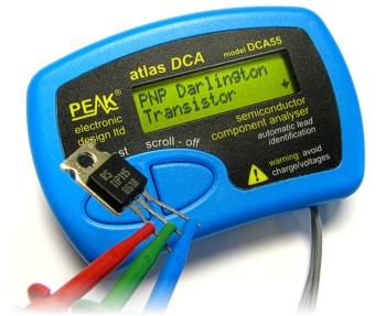 |
| COMPONENT ANALYSER |
 |
| INTEGRATED CIRCUIT |
Monday, 17 October 2011
This week class moved to a new level which is WORKSHOP. Its being taught not by Dr. Kamal but other lecturer. He is En. Ahmad Redzuan bin Mohd Hanapiah. He will be teach us for about 7 weeks and after that others lecturer will take over. Before i enter the class. I fell very excited because this class is more towards practical and me as boys really love when it comes to practical.
FIRST class is on 11th October, during this class En. Ahmad Redzuan explain to us about what are we will be doing throughout this 7 weeks. He tells us that during his class we will be deal with electronic apparatus such as diode, capacitor and transistor. All this electronic apparatus will be useful when we are making our own circuit board. En. Ahmad Redzuan also stress us about the 5S while we are deal with the apparatus.

SECOND class is on 13th October, we had our instrument test during this class. We only manage to test resistor and capacitor only due to limit of time. Resistor function is to resist current. Without resistor, voltage cannot flow and the circuit is not completed. We test resistor by observing the colour code. besides review to colour scheme, I also used multimeter to check the actual value of the resistor.
 |
| multimeter that i had been used to measured all the apparatus |
For capacitor, we actually test three type of capacitor which are disc ceramic capacitor, mica capacitor and radial capacitor. We measures the capacitors by using colour code, multimeter and by physical inspection.

We got three method to use because we need to test differend kind of capacitors. For mica type we used colour code, for ceramic capacitor we used physical inspection by looking at their code and compared its with the table provided while for radial capacitor we used multimeter. Actually, every electronic apparatus can be measured with the correct mutimeter. Im very enjoyed during this workshop and can’t wait for the next meeting.
Tuesday, 11 October 2011
*class of 6/10/2011*
This is Chinese proverb that means everything that we hear and see is not perfect without we do and understand on what we hear and see. On this class, Dr.Kamal had given brief about our presentation. We need to choose one electronic devices and briefly present our devices in front of our classmate. Besides that, Dr. Kamal also teach us about semiconductor, which is the heart of electronic devices that is made up of silicon. Silicon is being choose because its availability, inexpensive, easy to control and can be manufacture at high temperature.I HEAR AND I FORGET,I SEE AND I FORGET,I DO AND I UNDERSTAND.
Wednesday, 5 October 2011
Reflective Journal
WHY GOOD CONDUCT IMPORTANT AND RELATED TO SYSTEM ELECTRONIC
Me as an engineer need to have good conduct skill because this skill is important to ensure that I doing my jobs very efficient and follows all the rule that had been stated. For system electronic, good conduct is very crucial because system electronic involves everything from the smallest thing such as microchips to biggest things like satellite . Without good conduct all this electronic devices may crash or having some damage. Me as future engineer very likely to avoid all kind of this situation to happen and that why having a good conduct is very important to an engineer.

GOOD CONDUCT AND ITS RELATIONSHIP WITH ME AND MY LIFE
- In my student time, good conduct should be practice everyday to make sure that I can use it very well through out my whole life. Besides, having good conduct skill can improve my communication between people and will helps me a lot during my study or presentation time.
- For my future time, good conduct will help me to become an engineer that put priority on making a good and excellent system electronic devices for people usage. Good conduct can also increase my confident level to faced different types of people during my working time.
- Good conduct in everyday life is important to ensure that Ican have a nice public relationship. Family, friends will feel easy to hang out with me, talk to me or even to share their problem. By having good conduct skills, I can easily faced any difficulties through out my daily life.
 |
| good conduct is very important in our lives |
ALL IN ONE ( 29/9/2011)
All in one becoming my tittles post because my second class full of new knowledge and advise from our lecturer, Dr. Kamal about the important things in becoming an engineer. Introduction to electronic system course preparing its students based on program outcome and course outcome in order to ensure that our as future engineer can be adapt to any kind of situation. I'as going-to-be engineer is being expected to;
- using Bloom's taxonomy in my studying,
- develop my generic skills ,
- build up my self confidence and second nature,
In this class, I'm also being taught what is the differences between 'learn to serve' and 'learn to earn'. Its maybe sounds similar but the truth is there is huge differences between this two statement. Besides that, we also learn what is 5S, which is from Japanese words which means sorting, straightening, systematic cleaning (shine), standardizing, and sustaining.

Dr.Kamal also give me and my classmate lecture about the essence of belief, that consist of 5 main point which are faith, worship, monetary affairs, social conduct and good conduct. This essence of belief is important like the others that i have mention above. Thanks to Dr. Kamal who have introduce us very well about the world of engineering and this SMJE 1032 couse. =)
Saturday, 24 September 2011
the feeling of first day 22/9/2011
first day of my class => Introduction to Electronic System Engineering (ESE) is so exciting . Dr Kamal had given me and my classmate a good and further brief on what is electronic system. Beside Dr Kamal also teach us how to differentiate not number but our behavior + altitude + manner in order to became a successful student and also an engineer that can come up with brilliant ideas without put aside our good values in order to help people improve this world. Overall my first class is above my expectation even though some of us including me were late. We are very sorry for that. THANK YOU :)
Subscribe to:
Posts (Atom)